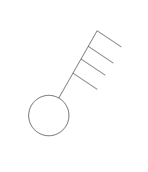
Unfamiliar electrical schematic symobol

I've been working with electrical schematics for quite some time, but I recently stumbled upon symbols representing loads that I'm not familiar with. Are these new additions or have they been around, and I've somehow missed them? Any insights would be greatly appreciated. Thanks!


Parents
  • It's a TP isolator. The Architectural ACAD symbol. If you zoom in on the schematic you can see the handle at the top ; the three diagonal bars donate three phases 

    regards burn 

  • The Architectural ACAD symbol.

    I'm not 100 % sure of the alignment with IEC 60617?

    The OP says it's on a schematic, and the later post is a schematic ... therefore I believe symbols should be as per IEC 60617-7-13-xx and be like the single-line diagram symbols I posted earlier (with "TPN" qualifier or similar)?

    However, if it's architectural (i.e. for use on floor plans and elevations to show rough location of equipment and controls in a room), IEC 60617-11-14-xx and a TNP (4-pole) switch, disconnector or isolator would look something like this, perhaps with a feature indicating it's an isolator.

    Can anyone confirm who has access to the current IEC 60617 database?

  • I didn't say it was in line with IEC 60617. Nowadays most of us working on larger scale construction projects have no choice but to use Autodesk products (ACAD 2D or Revit for BIM 3D modelling) and have to take what they give us. 

    regards burn

  • The great thing about standards is that there are so many of them to choose from!

  • The great thing about standards is that there are so many of them to choose from!

    Not in this case. BS 7671 specifically requires IEC 60617 (see Regulation 514.9.1)

  • I didn't say it was in line with IEC 60617.

    BS 7671 requires that standard, though.

    have no choice but to use Autodesk products (ACAD 2D or Revit for BIM 3D modelling) and have to take what they give us

    Yet if you are using the package to provide a design for an installation that had generators (including inverters) operating in parallel with the grid, or a switched alternative, ESQCR Regs 21 and/or 22 (as applicable) mandate BS 7671 ... so you have no choice but to use IEC 60617 symbols?

    However (and I might be mistaken on this) I thought certainly AutoCAD had a conformant library, the main issue being actually looking up which of the symbols is the correct one ... because they also have ANSI and other standards of symbols in there too ? The easiest solution, therefore, being a subscription to IEC 60617 to look up what you need to use AutoCAD because there isn't an internal "cross reference list" in the libraries?

  • I don't think the issue under discussion is driven by the need to use standard AutoCAD symbols.  We make our own symbol blocks and these can look however we want them to look.  Engineer's 'inventing' symbols on layouts to represent equipment that isn't in the company library regularly occurs - some not as intuative as we would like.  

    In terms of compliance with BS 7671 - Our LV schematic drawings are not intented to be produced for compliance with 514.9.1, but rather are used as indication of a design.  The level of detail of these is based around BSRIA BG6 document - i'm not sure if i am allowed to include a snip of their example drawing here to demonstrate the point, but BG6:2018, page 63 is a good example.

    I am not contesting that a diagram in accordance with 514.9 is not required - just that the diagram in the OP is probably not the one to use as evidence of compliance. 

    Pretty much every LV schematic i have seen designed by a building services consultant follows the form in the picture, and if i was to be issued that drawing excerpt, the symbols used wouldn't be the hill i'd by picking to die on.

  • That may be the case, but arguing any mis-interpretation of it later (actual, or "fabricated" when someone makes another mistake and wants something they can hang their hat on) can be quite costly.

    I also fail to understand the need to maintain a "house library" for things that are already defined - and often these end up being taken through to "as-builts".

  • If a defence to an incident was based on symbols on a schematic then I think that in itself would raise some questions and show some level of straw grasping.

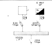
    If we were to look to what is accepted practice by a body of professionals, then symbols of the type used in the OP are widespread in the building services world, and i would argue - and give evidence- they are much more common than any alternative - I was on a site earlier and took a photo of the distribution schematic that dated to 1992 - excerpt below.  It shows the terminal points of the distribution network using the layout symbols, and in this case shows an isolator and a distribution board.   I have other sites stretching back further that use the same approach.  I could not find a single distribution schematic that did not follow this convention across any of my client's record information.

    The 'house' library is mainly used to ensure a consistent visual aproach in the symbols and text used, so they plot consistently.  Looking at what has been 'invented' in the library more recently, we have solar panels, EV chargers, AFDDs, key interlocks.  Maybe there are IEC versions of these.

  • It shows the terminal points of the distribution network using the layout symbols, and in this case shows an isolator and a distribution board.   I have other sites stretching back further that use the same approach.  I could not find a single distribution schematic that did not follow this convention across any of my client's record information.

    Agreed, I have seen similar things too, but that doesn't mean it conforms to BS 7671, and is the right thing to do.

    If a defence to an incident was based on symbols on a schematic then I think that in itself would raise some questions and show some level of straw grasping.

    It would be part of a wider picture of "disregard for safety standards", "non-compliance" or "non-conformity" (whichever you prefer). Especially where the diagram is provided in relation to Regulation 514.9.1 (iii).

    It's relatively easy to build such a picture. For example, a lot of organisations have electrical procedures that make the simple statement like "all tools to be insulated when working on or near electrical equipment, even equipment made dead" ... but we know it's common to use non-insulated mechanical tools on the "mechanical parts" of electrical machines and assemblies, e.g. socket-set to remove covers.

    Pick a number of similar things up, and it might paint a poor picture of operatives not working to safety rules, and management not enforcing them.

    The 'house' library is mainly used to ensure a consistent visual aproach in the symbols and text used, so they plot consistently.  Looking at what has been 'invented' in the library more recently, we have solar panels, EV chargers, AFDDs, key interlocks.  Maybe there are IEC versions of these.

    I think the issue here, is the cost to subscribe to the IEC 60617 library to find out (if it's not apparent from the CAD software library).

Reply
  • It shows the terminal points of the distribution network using the layout symbols, and in this case shows an isolator and a distribution board.   I have other sites stretching back further that use the same approach.  I could not find a single distribution schematic that did not follow this convention across any of my client's record information.

    Agreed, I have seen similar things too, but that doesn't mean it conforms to BS 7671, and is the right thing to do.

    If a defence to an incident was based on symbols on a schematic then I think that in itself would raise some questions and show some level of straw grasping.

    It would be part of a wider picture of "disregard for safety standards", "non-compliance" or "non-conformity" (whichever you prefer). Especially where the diagram is provided in relation to Regulation 514.9.1 (iii).

    It's relatively easy to build such a picture. For example, a lot of organisations have electrical procedures that make the simple statement like "all tools to be insulated when working on or near electrical equipment, even equipment made dead" ... but we know it's common to use non-insulated mechanical tools on the "mechanical parts" of electrical machines and assemblies, e.g. socket-set to remove covers.

    Pick a number of similar things up, and it might paint a poor picture of operatives not working to safety rules, and management not enforcing them.

    The 'house' library is mainly used to ensure a consistent visual aproach in the symbols and text used, so they plot consistently.  Looking at what has been 'invented' in the library more recently, we have solar panels, EV chargers, AFDDs, key interlocks.  Maybe there are IEC versions of these.

    I think the issue here, is the cost to subscribe to the IEC 60617 library to find out (if it's not apparent from the CAD software library).

Children
No Data