Do I take this into consideration? If so how do I size wire in a building with a safety generator? What is my "Ze" when the supply switches from DNO to the safety generator? How do diesel generators behave during faults?

perspicacious:
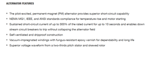
From the large print extract:
Generator can sustain 2.5 to 3 times rated current with a 3-phase fault applied for approximately 10 seconds without damage to alternator.
The alternator windings may well be able to, but I'm struggling to accept that the associated prime mover can produce 2.5 to 3 times it's rated output for a second, yet alone 10 seconds. What size is the flywheel?!!!!!
Regards
BOD
There is no flywheel. It just s diesel set with an alternator. Perhaps UK gensets can not export short circuit current to the same degree as foreign sets?
davezawadi (David Stone):
This is getting very confused. The engine will only produce its rated power assuming the frequency (RPM) is constant. All other associated power can only come from the rotating inertia of the engine and generator rotor. A complete short on most sizes of generators will stop the machine very quickly, perhaps 10 or 20 revolutions. The moment the engine speed falls so does its output power, power = torque x RPM, and the torque is limited at all speeds and gets less as the speed falls in most machines at limiting power output. Your document is probably not very accurate for most reasonable-sized generators say <500kVA. Also, the AVR is designed to reduce the excitation if the frequency falls, and usually to make it zero at 40Hz for a 50Hz machine to protect the mechanical parts from failure. The forces involved may be very large, sufficient to break generator shafts, or piston rods or the crankshaft with a low impedance short circuit. Such failures do occur in generator sets sometimes because those first few revolutions are critical, the short circuit current is not in any way "free", it is a real very large amount of power. Just because the short collapses the voltage does not reduce the real power in any way, the alternator is still making 230V or whatever, it is almost all lost in the windings and the external circuit as resistive loss, although perhaps 10% may be lost in the reactance.
I'm afraid Mike has made a slight slip, a synchronous alternator does not suffer "slip" as such, the output exactly follows the machine rotation at all speeds, in the same way that a separately excited motor does. Slip in an induction motor is simply to make the rotor magnetic field, in an alternator, this is externally applied DC and only controlled by the AVR. Small machines do sometimes operate as asynchronous machines but these have very poor overload and voltage control characteristics.
One further point is that most machines that are brushless depend on simulated transformer action to get the AVR excitation power to the rotor, where it is rectified and gives the rotor field. This is a very important part of our size of the machines under discussion. There are a number of various ways to do this, which are usually covered in Patents, it is easiest to just look on this as I suggest, although there may be a secondary alternator action or similar involved. It makes little difference to the operation.
How can the text extract not be accurate when coming from a reputable manufacturer? All the generator specs I'm looking at indicate that generators <500kw are capable of exporting short circuit current between 3x to 10x for some amount of seconds. For example, 300% for 10 seconds: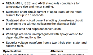
http://resources.kohler.com/power/kohler/industrial/pdf/g5438.pdf
I'm also confused when you say 10% will be lost to reactance when reactance itself is not real power. I'm also under the impression that reactance actually causes a generator speed up vs slow down.
davezawadi (David Stone):
Ah Mike, but I did specifically talk about synchronous machines! As it happens I do have a small generator of the asynchronous kind, but to be honest (and as I said) it is not very good at either constant frequency or constant voltage. All of the generators we are talking about are of the synchronous kind, and although other asynchronous types are available (and sometimes the military use them for other reasons) machines in the 25kVA and up are normally fully synchronous types.
I agree with you BOD, there is no way that a 100HP diesel can produce 300HP even for a second or two, I can get that much given a bigger turbo and a lot more fuel injection (and black smoke) and.... but it is not there in the standard model. The overload characteristics are only the inertia and the rated power, and if the speed reduces for whatever reason the power may be as rated for a small change, but much and it goes very quickly. Engines for generators are very different in "tuning" to that in a car, the speed is expected to be constant at a particular value, and the fuel consumption is minimised at that speed to the loss anywhere else, particularly of torque at higher or lower speed. In the generator world, fuel consumption is everything, it is entirely driven by operating cost. A typical generator for film or television lighting is a peculiar beast, it may well have an external television sync input, and be crystal controlled for frequency to 3 decimal places for frequency (which might even be 48 or 50Hz, or 29.970*2 in the US). It is easy to think all generators are the same, they are not, and ones that can sync up and work in parallel are much more complex than one might expect.
Is it possible that the engine can indeed output 300% power for a few seconds? Or that the AVR ramps down the voltage but keep the current high in the fault loop such that the engine is loaded to 125% instead of 300%? Or the reactance of the fault might not actually load the engine up to 300%?
It has to be one or a combination of all 3, but to be honest I'm confused more than anyone else.
davezawadi (David Stone):
Interesting, because you have answered your own query. These are permanent magnet alternators and probably on very small machines with oversized engines. A short circuit on a conventional (synchronous) alternator will remove the voltage from the AVR (which is powered from the output terminals in most designs), thus removing most of the magnetic field from the rotor. This is a deliberate safety feature to prevent winding damage and mechanical failure. All the other details there suggest that these machines are intended to live a hard life outside, The data missing is how the voltage control works, although there could be some clue from the pilot-excited phrase suggesting that the permanent magnets only give some of the rotor field, the rest being from an AVR. The superior waveform claim is curious too, the rotor design normally is modified to give excellent waveforms from the machines I have seen, often a very small harmonic content with a resistive load. Bad loads can of course change this, but this is not really a function of the alternator. Please post the spec or a link for the data you are quoting, I would like to see exactly what we are discussing.
Well, don't think its answered for certain. I mean I don't know what the output voltage will be at those 300% amps is. In theory lower voltage means less current through a given impedance, so resistance or reactance from the conductors could limit current below 300%. I don't know for sure.
Here is the PDF:
http://resources.kohler.com/power/kohler/industrial/pdf/g5620.pdf
Here is site listing:
https://kohlerpower.com/en/generators/industrial/product/400reozjc
davezawadi (David Stone):
<snip>... These are permanent magnet alternators and probably on very small machines with oversized engines. A short circuit on a conventional (synchronous) alternator will remove the voltage from the AVR (which is powered from the output terminals in most designs), thus removing most of the magnetic field from the rotor. This is a deliberate safety feature to prevent winding damage and mechanical failure. All the other details there suggest that these machines are intended to live a hard life outside, The data missing is how the voltage control works, although there could be some clue from the pilot-excited phrase suggesting that the permanent magnets only give some of the rotor field, the rest being from an AVR. <snip>
I suspect it is more like one of these.
The permanent magnet part is really only a big brother of a bicycle dynamo in that it provides the 'pilot power' that is AC that is then rectified to provide DC power to the electronics in the AVR controller that is setting the Exciter field, and perhaps to supply some ancillary electronics for engine management and cranking battery condition as well. The AVR senses voltage and current readings from the outbound phases to decide exciter level, but is not depending on it for the excitation power to the armature.
The fact that the AVR does not lose its supply when the output voltage collapses is both a benefit and a risk, as you point out, depending on the avr details it keeps going in fault state, but it also recovers more gracefully with spiky loads
The bigger machines by Brush all work on this basis.
It does also mean that clever microprocessor controls and telemetry stay up as well, and cannot be crashed by load side abuse, and that is essential in some more automated settings when either motoring in extra generation or generator shedding from afar.
Mike.
ProMbrooke:
Here is a similar genset being tested during re-sell. Admiting this particular model unit bogs down way more than they typically do when accepting 100% load.
https://www.youtube.com/watch?v=K0U7wsZgbZY
Actually in my experience they all do that to some degree, and buried in the spec is usually something about maximum load step without loss of regulation, which may be around half of full load. If you need to support more load instantly, you need a bigger machine and under-run it.
The ISO call that test "load acceptance" more here.
M.
We're about to take you to the IET registration website. Don't worry though, you'll be sent straight back to the community after completing the registration.
Continue to the IET registration site