This discussion is locked.
You cannot post a reply to this discussion. If you have a question start a new discussion

Type A rcd . EICR coding ? etc

Hi Guys.   Not been on for a long time, just had a bit of a search and couldn't really find anything so thought i would ask and see what you all thought.


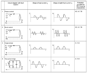
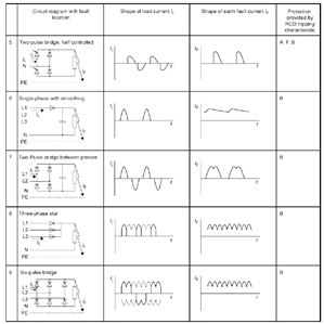
1.  Are we or will we be coding type AC rcd's if there are LED's or induction hobs, lots of electronics  etc  present.

2. How much DC leakage does it actually take to saturate an rcd and cause  problem?

3. How much does a standard LED lamp or induction hob  leak ?

If we test an AC RCD with no load and it's fine then re-test it with all LED lights, induction hobs etc turned on and it operates correctly could we then say that it is ok with a note on EICR  OR EIC if installing any of the above.  


Obviously also on an EICR if the RCD then doesn't operate with it all on it becomes a C2 ?


Any thoughts


Gary
  • I agree Jon, and a lot of this is based on faulty guesswork as to how these devices operate.

    Let us discuss from first principles. Is it possible to get a DC current from an AC supply? This depends on our definition of DC, which is not often clear from RCD manufacturers. My definition is quite simple, DC is a relatively constant voltage or current, which does not vary with time, in other words, a battery. An AC voltage or current is a supply that varies about zero volts in a regular manner in time. Now we get the fuzzy bit, which is an asymmetric AC waveform that is not symmetric about zero and may vary between cycles in some manner. This is the waveform produced by a half-wave rectifier feeding a capacitor, as an example. Current only flows in one direction but is certainly not proper DC as defined above. Next we need to examine the effect of these waveforms on a transformer with two windings connected in opposition. Windings like this give exactly opposite magnetic fields and the net in the core is zero. The result should be that any net magnetic field can be transferred to a third winding by the core, which is then detected as a difference current, and used to make an RCD. Equal DC current in both windings should again cause cancellation of the magnetic field in the core, but any difference will not be transferred to the third winding as transformers need an alternating field to operate. This is the theory.


    Now the difficult part, which is how real devices vary from the theory above. It is possible to put two similar windings on a magnetic core in various ways to achieve the theory above. They can be spaced from one another, by a distance as long as they both have the same number of turns, and will work as above with nice waveforms. However, once the waveform has more components at higher frequencies, things get more complex. Magnetic cores are not ideal and have losses, and coils do not couple to them in an ideal way. These two together are usually considered in power engineering as leakage inductance, a measure of how far from ideal a transformer is. It can never be made zero, particularly at low frequencies (50 Hz). It is a measure of how much of the magnetic field fails to couple the two windings and is lost. In an RCD we can wind our a small core with two separate windings or wind them together as a bifilar winding where the two wires are as close to one another as possible on each turn. In RF transformers we also twist the two wires together to improve coupling further and improve the exact balance of the current. As there is a significant voltage between the wires in an RCD, closeness is a problem. The closer the windings the less likely that the waveform will not be transformed as required, or the core cause a problem of coupling. Note a real DC current on L & N should also exactly cancel so the core cannot become saturated.


    Next, the DC thing, which seems to focus minds a great deal, I'm not sure why. The question: Can I get a significant DC current through just one winding to saturate the core with a real load? Core saturation prevents normal transformer action and may prevent the difference signal being detected by the sense winding, so prevent operation at least at normal sensitivity. So far I have been unable to come up with any load which can generate such a DC current for more than one cycle, (as may be used in "no trip" tests). Even this is fairly tricky, and certainly nothing like any electronic power supply design. Therefore I consider this DC consideration a rather "RED Herring", and needs a manufacturer to describe how they think this is a problem. I can find no explanation in technical terms anywhere else!


    David CEng etc.
  • My definition is quite simple, DC is a relatively constant voltage or current, which does not vary with time, in other words, a battery.

    Shades of the old "direct current" vs "continuous current" word war of yesteryear. I think the outcome was that d.c. could include ripple (i.e. could include a waveform, but overall it didn't cross zero - i.e. the polarity never alternated) while c.c. was your battery output. But the exact words don't matter as long as we userstand the meaning. Continuous current seem to be out of fashion these days so we have d.c. (sorry DC) and ripple-free DC.

    needs a manufacturer to describe how they think this is a problem

    I agree - there's still far too much confusion at the moment.


    So far it seems to me that there might be several different effects/symptoms/problems going on. There's the issue of DC saturating the coil and blinding the RCD to real faults (for which one fix seems to be a B-type RCD), But there also seems to be a separate issue of the fault current itself not being a complete a.c. waveform - e.g. a L-PE fault after a rectifier - which (allegedly) AC RCDs aren't guaranteed to be sensitive to. On a TN system I'd imagine that a L-PE short after a rectifier, if the RCD or OPD didn't disconnect, would blow the rectifier to smithereens in pretty short order and likely achieve some kind of disconnection fairly quickly anyway. On a TT system with potentially very low earth fault currents, it's seems possible that we'd end up with an uncleared fault. That I think is the sort of thing they're pushing A-type RCDs for.


       - Andy.
  • Hi Andy. In your examples, there is still no DC current.  DC may have some ripple as you say but the current direction never changes. A short after the half-wave rectifier does not produce a DC current, the AC waveform is still a current changing at the supply frequency. This will operate the transformer just fine, as the L-N currents are identical and the transformer is not saturated, because they should cancel exactly except for an Earth leakage fault (which we aim to detect). It could be that the short pulses of current produced by a rectifier-capacitor arrangement may not cause a trip, but this is a problem with the design/specification, not the device itself, and certainly, isn't DC. I am beginning to wonder if this is the problem that manufacturers are attempting to cover up because as I said, there seems to be no information on this "DC" problem.
  • I don't know if these help at all (from BS 7671 of all places):

    3804e77bdc28f6126d0e78e048840f6f-original-rcdwaveforms1.png
    395c5fc595e6b715819a551e06b3cc2b-original-rcdwaveforms2.png


       - Andy.
  • Once again it appears to me that the good old British have latched onto an idea and are going completely over the top with it.


    Why do British electricians and others think that there is a major problem with Type AC RCDs and only Type A should be installed in domestic installations, when elesewhere in Europe the requirement is to have one of each?


    ”What should be connected to a type A differential switch?


    A differential switch is a modular device intended to be placed in the electrical panel. Its purpose is to protect people against electrical hazards. The N FC 15-100 standard requires the installation of a minimum of two differential switches per housing, in the electrical panel. One must be AC type and protect standard circuits. The other must be type A. What should you plug into this type A differential switch? What does it protect?


    What is a differential switch?


    First of all, it is necessary to recall the operation and usefulness of a differential switch. This modular device is placed in the electrical panel, between the general circuit breaker and the branch circuit breakers.


    Its goal ? Protect people from the risk of electric shock, while circuit breakers are there to detect overloads and short circuits - and shut off the circuit if necessary. It can protect up to 8 circuits, themselves secured by individual circuit breakers.


    The differential switch cuts off when the difference between the incoming and outgoing current is greater than 30 mA (milliamps), because the electrical current can be dangerous for people above 50 mA. This is called a current leak.


    The rating is measured in amperes and corresponds to the maximum current that the differential switch can withstand. You should know that the type of switch has no impact on the sensitivity or the intensity. A type A can withstand 25A, 40A or 63A, just like an AC type; and all display 30mA.


    What should be connected to a type A differential switch?


    The type A differential switch is therefore designed to protect circuits associated with devices creating direct currents, in particular hobs, washing machines and the charging socket of an electric vehicle.


    The N FC 15-100 standard requires these devices to be connected to a dedicated circuit protected by a type A differential switch, with a sensitivity of 30 mA. But that's not all: it also recommends associating only a maximum of 8 circuits with each differential switch.


    In addition, all housing must be protected by two differential switches (one AC and one A). It is strongly recommended to divide the lighting circuits and outlets under two switches, so as to ensure continuous operation of the lights and appliances.


    Remember to test your RCDs regularly - regardless of the type! You must ensure that they are functioning properly, otherwise they will not be able to ensure the safety of the occupants of the accommodation.


    Many devices can be placed under the type A differential switch but the NF C 15-100 standard requires at least the following devices: hobs, washing machine and electric vehicle charging socket.


    The different types of differential switches


    Since it comes down to figuring out what can be plugged into a Type A differential switch, that means there are several. Here are which ones:

    The AC type is designed to protect common circuits, in particular sockets and lighting, but also most installations (oven, fridge, VMC, etc.). This differential switch detects AC component faults.

    Type A protects special circuits, designed to be associated with particular devices. This differential switch detects AC and DC component faults.

    Type F is intended for the protection of devices sensitive to electrical micro-cuts (freezers, computers, etc.). We speak of a "high immune power" differential switch. It detects AC and DC component faults, as well as high frequency fault currents.


    Take a look at the selection guide dedicated to electrical panels and circuit breakers to discover the different types of residual current devices.”

    https://www.legrand.fr/questions-frequentes/que-doit-on-brancher-sur-un-interrupteur-differentiel-de-type-a


  • Maybe the French manufacturers influence their own regulations.
  • Jon Steward:

    Maybe the French manufacturers influence their own regulations. 


    An A and an AC, plus possibly a F.


    That sounds like a considered approach, rather than rushing to install all A.


    Andy  


  • Sparkingchip:
    https://www.legrand.fr/questions-frequentes/que-doit-on-brancher-sur-un-interrupteur-differentiel-de-type-a


    Merci à l'oncle Google pour ce traduction !


  • ?