This discussion is locked.
You cannot post a reply to this discussion. If you have a question start a new discussion

Unusual Earthing System

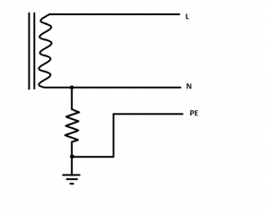
One of the Cahier Technique papers talked about an earthing system, which it described variously as cross between TT and TN-S or an 'impedance earthed TN-S' system, although I don't think either description is particularly accurate. Basically it suggests earthing the supply star point via an impedance, but then Earthing the consumer systems to the same electrode as the source:

66c3de7fa1842c6eefc0499bb3bad3a7-huge-notttnortn-s.png


As earth fault currents would be low, you'd need RCDs for ADS (just like a TT system), but the way the earthing is connected would seem to give a number of advantages over normal TT or TN systems. The most obvious perhaps is that exposed-conductive-parts remain at (or very close to) true Earth potential even during a L-PE fault - substantially reducing the risks of shock (even for the 5% of the population who aren't necessarily safe under normal ADS) - unlike a TN system where the point of the fault is likely to be at around half the line voltage, and in a TT system anything up to the full line voltage. It also less of an immediate issue if an RCD is a bit sticky or even fails to open altogether. They also claim less risk of damage or fire from L-PE faults than on TN systems - as the fault current is so much reduced.


So firstly what should this system be called? The impedance at the source is like an IT system - but the "T" would mean the consumer has their own earth electrode independent of the source's - which very specifically isn't the case here. Neither is the consumer's PE conductors directly connected to the system neutral which an "N" would usually indicate. As far as I know there isn't a letter to say the consumer's earth is connected directly to the supply's means of earthing (and not N) - maybe we could use "E" or "PE" for that - making it a IPE or IE system? I'm sure there are some better ideas out there.


My other thought was how would such an arrangement fair from the point of view of things like EMI or the effectiveness of SPDs - would it make any difference?


   - Andy.
  • Former Community Member
    0 Former Community Member
    It's not a wide spread system type, but I do know of several manufacturing plants that use impedance earthed systems for the plant production power systems - these have combinations of operating as IT or TN systems depending on requirements - eg they may have an earthing resistor imposed to limit fault current and reduce cable screen or earthing conductor sizes to manageable sizes and/or operate as true IT systems with insulation monitoring and no disconnection on "first fault" conditions. I can think of several that operate as 680V systems (particularly where the owner has manufacturing capability in a number of different countries and can standardise on equipment)


    From Alan's post above, it should be apparent that selection of 6.35 Ohms as a resistor value reflects the phase to earth voltage of an 11kV System with a desired 1000A earth fault current limit - that resistor may be as simple as a water tank with a defined concentration of bleach added (so called LER's)


    Regards


    OMS
  • I came across this system at a large plant in Algeria in the 1970s. It would have been based on French standards from the 1960s. I don't know if it still used either in Algeria or France.

    The obvious advantage is that it will survive one PE fault and continue to supply power but there should be an alarm fitted to indicate any large N E voltage which allows faults to be investigated and cleared quickly.

    The downside to this is that faults can only be located by turning off the circuits one by one which rather negates the benefit of not having the fault trip the local breaker immediately as in a UK system.