This discussion is locked.
You cannot post a reply to this discussion. If you have a question start a new discussion

Earthing and the radio amateur

I've recently joined the IET forums. I replied to a  topic regarding amateur radio and PME on the old forum. Unfortunately I cant access the old forum anymore so I thought it would be best to start a new topic.


So. On the bench there is a transceiver with a metal case. Next to the transceiver there is a antenna tuning unit which is connected to a antenna system which is using an earth rod. Am I right in saying there is a chance of a potential difference between the two metal cases of the equipment regardless if it is a TT, TNS or TNCS?


What would be the ideal solution?  Put the shack on it's own TT supply and bond all the radio equipment back to the MET of the TT and if a earth rod is used for the antennas connect that back to the MET also?


If the TT system was not an option what would be best if the supply was a PME and you didn't want to use balanced antennas removing the use of an earth rod? 


To be honest I've never really given PME's and amateur radio much thought which in hindsight was probably a mistake. I do remember when I did my training an earth rod was recommended for the radios.


Apologies for being so random.


Stewart M0SDM
  • A frfiend of mine did some earth bonding a few years ago and he was told on inspection that you were allowed to count copper pipes as an earth connection as long as the joints were soldered or compression fittings.


    If that is still the case, could I bond my earth rod to an outdoor central heating drain tap just two metres away? ?.


    Mike


  • A frfiend of mine did some earth bonding a few years ago and he was told on inspection that you were allowed to count copper pipes as an earth connection as long as the joints were soldered or compression fittings.


    If that is still the case, could I bond my earth rod to an outdoor central heating drain tap just two metres away?

    The advent of plastic (push fit) plumbing fittings used for alterations and repairs makes such assumptions a lot less safe than they used to be - so generally now we expect bonding (as distinct from earthing) connections to at the boundary of the equipotential zone (or as close as practical) - that way such plumbing changes can't undermine the effectiveness of the bonding. The regs so of do permit metallic pipework etc to be used as part of a protective conductor - but require precautions to be taken against its removal - which is going to be tricky in an uncontrolled environment like a domestic. If you had to expose and label every separately visible section of the pipe with a suitable warning, you'd probably find that dragging though a bit of G/Y wasn't so daunting after all.


    I'm not sure like the idea of a central heating drain cock being outside anyway - how do you stop it freezing in winter and splitting the pipework/fittings?


      - Andy.
  • Thanks Andy, I thought that might be the case. I've read so many different views on this that I am going to take the path of least resistance (pun intended) and bond the rod to the MET. The only problem with that is the G/Y will be 12 metres long as the wife will not allow me to take up any more floors ?. I'm assuming that that is covered by Part P and will therefore need to be inspected, yes?


    As for the drain tap, I wouldn't have put it there either but the house was built 50 years ago and it hasn't frozen yet!


    Mike
  • it is covered by part P in the sense of being domestic work , but is not on the notifiable list, and will NOT  need to be inspected - your call is not a MW so you are not in Wales, in England such work is non-notifiable.

  • mapj1:

    it is covered by part P in the sense of being domestic work , but is not on the notifiable list, and will NOT  need to be inspected - your call is not a MW so you are not in Wales, in England such work is non-notifiable.


    Thank you! ?

  • I am currently running 100W of SSB into dipole in the loft with a 1:1 balun. I tried to work on the 5MHz band recently but on receive other stations were underneath 7 S points of noise. I can work 14MHz with generally around 3 S points of noise. Propagation conditions are pants and looking forward to a change in sunspot activity.


    I have entered a circular planning phase for an outside aerial to replace my loft dipole. I would prefer something multi band and have considered an end fed wire in to an AMU with an external earth rod. I have a couple of AMUs including a very nice ex military Clansman unit. My concern is RF radiation in my office upsetting my computer and periferals.


    Any advice on a multi band HF aerial for a house with a short garden that has a low visual impact? Or should I give up and just erect a dipole for 14MHz with a 1:1 balun outside?


    Also I have a roll of 10mm single black conductor. should I leave the insulation on or strip it for less weight, lower wind loading needing less support and visual appeal?


    JP G8NUP
  • At the risk of telling you what you already know.

    On HF, any wire antenna, even one that is random length and pulled in by ATU, will not benefit much from fat wire. Anything more than about 0.75mm2 will be self supporting unless you want to dangle a big box with a trap in the middle of it mid span. Ends of dipole antennas can come down to be a few feet above ground before switching from wire to insulating cord, and form an  "inverted V" so you only need a single central pole, that can be metal or insulating, but more importantly, quite thin and guyed. Trees work well, so long as the wire elements do not rub the branches, and the fixings at the other and can be arranged to accept the movement in the wind.

    In terms of stealth, for the UK, white grey or black PVC insulation is are more or  less as good as each other against the typical (summer) sky.

    If you have planning issues, I presume you have neighbours who are not on-side ? If you are on good terms and are able to set peoples minds at rest that they are not all going to be fried or struck by lightning and invite them to see it in action, this can help a lot.

    In adversity, then there are 2 approaches, either it it is there for less than 28 days in the calandar year, so it needs no permission (ideal for trying out different designs quickly, a sort of guerrilla approach, bit like lots of field days or JOTAs), or if you can,  putting the antenna up, taking a dated photo with something that ages (small children are good) in the background as proof, and hoping no one complains in the first 4 years. After that has expired, so long as you do not take it down or change it substantially, you are in the clear. Some local authorities are more keen than others on enforcement, and some need reminding of the 4 year rule, but it is there. Note that  ff you are an RSGB member there is quite a bit of planning advice on-line on the members site.

    Anything working against an earth electrode needs serious thought about managing the return currents, as the earth will be 'hot' during transmission,  you are right to consider EMC as a possible issue, also bear in mind ground resistance losses can take a significant chunk out  of your useful TX power.

    In a high QRM situation, many receivers do better with an attenuator up front - it seems counter intuitive, but generally communications receivers  are optimised for weak signals, and overloading input stages designed for micro-volt levels just leads to odd mixing effects in the stages prior to the channel filtering - and once mixed in, it cannot be unmixed.


  • I might be able to help you here John. I have a smallish garden which is also my wife's pride and joy, so she won't give me planning permission for towers, beams or guy ropes Frowning2.


    I have put up an end fed half wave HF antenna. It is 20.1 metres long and runs from the house to a pole attached to a pergola, then across to the roof of our summer house (i.e. L shaped). The wire is 1.6mm hard drawn copper, and I sprayed the pole olive drab to blend in with the trees. The antenna height is approximately 4 metres and it is very hard to see.


    Now for the interesting bit. It is fed from the house end via a 49:1 unun. From there a metre of RG58 coax connects to a line choke then a further 7 metres runs to the shack, which is upstairs. The 1 metre length acts as a counterpoise for the antenna. The coax shield on the "cold" side of the line choke is connected to a ground rod to drain static electricity. The ground rod is also bonded via a line choke to the property's main earth terminal.


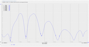
    I measured the antenna's VSWR with an analyser and the results on 40, 20, 15 and 10 metres are below. I use an LDG automatic tuner to improve it further and 100 watts SSB. There is no RF earth in the shack due to its height above ground, and absolutely no RFI. The first time I tried it the TV picture died, but that was due to poor filtering on the DAB radio input of my distribution amplifier in the loft. A 50MHz HPF fixed that.


    The results are impressive. I have had a 5/9 report from 1200 miles away in Bulgaria.


    Mike G8GYW


    2a71a008c423b121fee00491c7167ac4-huge-antenna.png

  • Mike (MAP)


    I have a roll of 10mm on the shelf I was thinking of using but did not know whether to strip it or not? I thought the larger the CSA the wider the bandwidth but didn't squat when compared to a bird cage dipole.


    Mike (D)


    I am very interested in your end fed. I have a 9:1 Unen I had thought of using but was unaware of a 49:1, what made you choose this?


    i have found an HF line choke on EBay with a SO239 on each end. Is this what you used? Did you just connect on to the co-ax braid for the earth connection to your electrode on the TX.  Side of choke?


    What choke did you use for connection to the installation earth?


    My Kenwood transceiver has a built in ATU does your TX. have an inbuilt ATU or not hence the auto ATU?


    How does the aerial perform on 5 MHz?


    Why 20.1 m length? That appears to be 1/2 wave at 7MHz?


    Sorry a lot of questions there?


  • John


    A 9:1 unun can be effective when used with a random wire antenna (i.e. one which is not a half wavelength at any frequency you want to work).


    However, the advantage of an end fed half wave antenna is that the feed point impedance is much higher (hence the 49:1 unun) and the VSWR is therefore less susceptible to influence by the proximity of the ground or buildings. This was a factor in my choice as I don't have much height to play with. My wire is indeed a half wavelength at 7MHz but as you can see from the graph it also has good VSWR at 14, 21 and 28MHz. My transceiver is a vintage Yaesu FT-840 which does not have a built in tuner, hence the external LDG. Your built in tuner should have  no trouble with the VSWRs that I'm getting. I haven't tried the antenna at 5MHz but I believe that by adding a 110uH loading coil and an additional 2 metres of wire it should tune up at 80 metres. That's a project for another day.


    The radiation pattern is definitely biased upwards, which explains my good contacts with central and eastern Europe, but also the fact that the nearest QSO I've had was 350 miles away in Scotland. I haven't heard any English amateurs yet!


    The coaxial line choke needs to be good quality. I used this one, and modified it by adding an earth lug to the box which is connected internally to the coax shield on the TX side of the choke:

    https://www.hamgoodies.co.uk/g5rv-choke-balun-400w


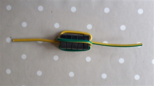
    This is the line choke I made for the bonding wire from the rf ground rod to the main earth terminal. The toroids are type 43 from the RSGB shop with 4 turns:

    8dc67703804bbb3c724a169e74255e60-huge-line-filter-1.jpg


    I hope that helps.


    Mike G8GYW