This discussion is locked.
You cannot post a reply to this discussion. If you have a question start a new discussion

DC injection braking and a burned out transformer

I have been fettling a lathe which was fitted with DC injection braking. I was a bit unsure about the condition of the components in an enclosure on the back, but having looked up a bit about motor control circuits and having learned about ladder diagrams, I have satisfied myself that I know what has happened.


At some stage, a transformer (240/130V) has burned out. That leaves two questions: (1) why? and (2) what is the spec of the old one?


The horizontal surfaces of the enclosure and its contents have been covered by a thin brown layer, which I assume is vapourised enamel from the transformer windings, but there is no evidence of any further damage.


Father taught me never to replace a fuse without finding the fault which blew it. Along the same lines, I want to be satisfied that none of the other components has caused a short circuit. However, it appears that it is the primary which has overheated. So my first question is what would happen if the secondary of a transformer is shorted. Would it be fried? Woud the primary be fried? Or would both be fried?


My second difficulty is determining the spec of the transformer. The circuit diagram has "N" and "240" on the primary side, and "Z" and "130" on the secondary side. I assume that this means that the secondary provides 130 V, which after rectification, is fed to the motor. The problem is that there are no markings on the transformer. The manufacturer of the unit ceased trading 10+ years ago, so no help there. The motor plate specifies 6.4/3.7 A. The transformer wires (both sides) are about 4.2 sqmm CSA so good for 3 - 5 A (?). Based on a weight of 4.0 kg and the transformer's dimensions, and comparing them with current models; I am guessing that a 320 VA transformer is required. My second question is whether my above reasoning is sound.


Before anybody else says it, yes, I think that I could get a modern module which will do the job, but isn't it more satisfying to fix rather than replace?
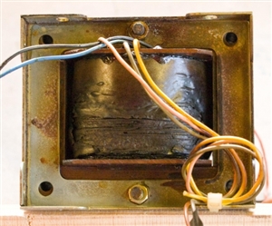
eabde54935c495ab8feb4fb009758b5e-huge-20190425transformer.jpg

  • of side interest , there are other ways of slowing an AC machine, including to put a capacitance and a load  accross it so it becomes an induction generator - this is most effective at higher speeds, as the generated voltage is speed dependant, and DC injection is better at stopping the shaft dead when it is already slowing.

    various patents have expired .

     DC braking 1958  dc we understand

    combining the bet of two methods DC braking which unlike normal DC injection,  still works in a powercut.
     

     1948 auto generator DC breaking 
    In accordance with the present invention, direct current for dynamic braking of the rotor 11 following interruption of the line circuits at the contacts 14 is derived from the kinetic energy of the rotor itself thereby avoiding the use of external power for dynamic braking.  

    I suspect with modern polymer film capacitors for generation and electrolytics for the DC smoothing capacitor this has become a lot more practical now than it would have been when first proposed - a set of  60uF paper capacitors for half horse power at 220v phase to phase would have added a significant volume and cost.
  • I have stripped down the lathe, replaced bearings and seals, etc., and turned my attention back to the electrics this weekend.


    I have replaced the transformer and the DIB works, but it is terribly fierce and brings the spindle to a dead stop almost instantaneously. (This brief clip shows a similar lathe stopping quickly - just before the end.)


    The new transformer is rather bigger than the old one, so I may have over-egged the pudding, but would the lower resistance in the secondary (0.49 Ω as opposed to 1.16 Ω) make much difference? I selected a 230/110 V transformer and it is giving an output of 116 V today.


    Then I wondered whether the wiring diagram might be wrong - was the output voltage in error? So I unwound the old transformer, which was a messy and tedious job with all the scorched paper and so on. The secondary had 123 turns of 21 SWG. The outer part of the primary had 29 + 55 + 268 turns of 28 SWG plus a further 352 turns of 25 SWG. It was this innermost part with the thicker wire that was connected. With 240 V input, that gives 84 V output, which is not consistent with the wiring diagram's figure of 130 V, but not grossly different from the new set up.


    Looking online, I have found a few references which suggest that the DC current should be 2 - 2.5 x the full load current. The motor's plate gives 6.4/3.7 A at 240/415 V respectively. 6.4 x 2.5 = 16 A and in fact I measured the max current as 17 A over about 2 seconds when the brake is applied, so again, not grossly excessive.


    Now what should I do? I think that the brake needs to be tamed somewhat. I don't want to go to the expense of buying another transformer if I can help it, but I was wondering whether to put something like a 4 Ω resistor in the braking circuit.


    Sensible advice gratefully received.
  • Maybe a reactive impedance (choke or the primary of another transformer in the primary ? Or even as it's not loaded very often... a heating element or high wattage lamp used as a ballast in the primary?
  • Glad you have restored it to operation, though it sounds like a bit of a beast, perhaps, given they could not draw a bridge rectifier correctly, the maker's datasheet was muddied with figures for a larger model. Thinking in terms of not cooking things, what stops the DC flowing  when it is all stationary and  no longer needed ?

    The stopping force is proportional to the B field, in turn proportional to the DC current so yes  some peak current limit in the form of a resistance on the DC side would do. I'd be less sure of using any resistance in series with the transformer primary, as while the brake is not applied the transformer load is almost nil, so the voltage reduction is not very much at the instant the brakes come on, and yet may be too much once the braking current has started to flow. Equally having a sharp initial brake, and then a more gentle slow-down may be quite acceptable.


    Or, as a quick try out, if you have 110v in the shop, how well does it work with that on the primary instead of 240? That would show you the effect of halving the voltage, and the voltage division would not be so load dependant. I might try a lamp dimmer, but not all designs of dimmer are happy on an inductive load. The simplest is resistance on the load side, and wire wound resistors of the metal clad kind are very forgiving of gross overloads (being little more than a heating element cast in ceramic in a metal tube ) Resistors that are a light evaporation of metal or other conductor on a ceramic rod (metal film / carbon film) tend to be self-fusing in overload, so I'd avoid those.


    Estimating the resistor values may be a bit odd, as you may think that one looks at the voltage and the windings resistance and there are the amps, but the  winding is a bit of a complex thing, and really the current will build slowly though the inductance.  You may think you need 10A, and at 110V, a total of 11 ohms will do, but that is not the full story,  so some experiment may be needed. You  may want to design a dropper with a no of higher value resistors in parallel, both to allow  some adjustment, and to provide  some be robustness against any single failure.


  • mapj1:

    Glad you have restored it to operation, though it sounds like a bit of a beast, perhaps, given they could not draw a bridge rectifier correctly, the maker's datasheet was muddied with figures for a larger model. Thinking in terms of not cooking things, what stops the DC flowing  when it is all stationary and  no longer needed ?


    Mike, thank you for your typically helpful contribution.


    This was the company's only lathe which was fitted with DIB. Unfortunately, they went out of business 10 years ago, so no help available there.


    A series of contactors ensure that the brake cannot be applied when the motor is drawing power, but that it is applied when the motor is switched off. Then there is a device which allows the braking current to flow for up to 20 seconds (I have it set to 2 sec) after which there is the reassuring clunk of a contactor opening.


    It would be useful to know what happened in the past. I am a bit concerned by the motor. Sometimes it runs reasonably smoothly, sometimes it vibrates, and sometimes it has intermittent brief judders. I have replaced the bearings so I wonder whether the windings have deteriorated. Or could it perhaps be the variable speed drive?

  • Interesting background, but as you say, not that helpful. I wonder how much of a 'development model' that brake really was.

    Certainly cut the DC as soon as you no longer need it, any more just heats things and eats into the restarts per hour budget.

    Judder is not a normally a winding symptom on induction motors.

    The VSD may have certain critical speeds that give resonances I suppose.


  • mapj1:

    Judder is not a normally a winding symptom on induction motors.


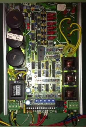
    If it's not the motor, it must be the VSD. Come to think of it, the juddering is rather like an intermittent misfire in a car. Could one of those big capacitors be failing?

    eb5645d9ed45225a0303181fe3358e7e-huge-20190619vsd.jpg


  • kellyselectric:

    It could well be a one or more of those caps failing they were made in 1989 if I read the datecode correctly  they look like the ones we made here in Weymouth at BHC components it I would be interested to know if they are from that manufacturer brings back not so happy memorys


    Kelly, you are spot on. Yes BHC. If 8943 means 3 April 1989, it fits with the date of the lathe which is circa 1991.


    Unfortunately RS says that this particular component has been discontinued.

  • The caps may be losing capacitance, but unless  they are bulging alarmingly then it is no biggy to substitute a similar part or if that is hard then leave them in and add some more uF in parallel. However, It looks like they are in parallel, what is the value/ voltage ?


    I have also had solder joints fail where fat legged components are held to the board, or fracture the track close to the solder blob, especially parts that run hot like the switching transistors. A bit of prodding with an insulated stick may reveal more - the old TV service technique of hitting things with the plastic handle of the screw driver to narrow down the are of a poor joint requires some nerve but can be revealing.

    Beware of damaging those orange encapsulated hybrids that seem to be doing the HV isolating the drive to the transistors- under the goo  is a small substrate and very small components, and some models of the things can be as rare as hen's teeth.


    IF you want to be sure it is the VFD, run the motor off 50Hz direct for a bit, or put 3 lamps on the VFD and see if they flicker when it misfires.
  • Mike and Kelly, thank you for your help.


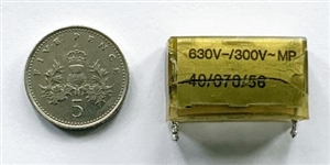
    I have tested the three big capacitors, which are indeed in parallel, and they are within spec. They are 470 μF and 385 V. However, the capacitor below is clearly not happy so whilst the board was out, I thought that I should replace it. It gives a reading of 0.5 μF against a spec of 0.1 μF. Whether it is the cause of the problem remains to be established. I cannot see any other obvious faults.


    I had thought of plugging in the motor direct. It would be a bit of a faff. Is it safe to plug it in and switch on?

    be5ea5c38056a46421b6fd8e43e511c1-huge-209dc6a9-21f2-4ec1-83b3-6056e2d6a76a.jpg