This discussion is locked.
You cannot post a reply to this discussion. If you have a question start a new discussion

Changing the power adapter some guidance on what to select.

Former Community Member
I received my PC Nailer from the US this morning, however the charger is a 120v US version not dual voltage, and I want to change it.  Was thinking that rather than buying the UK model which would either be the Stanley or Black and Decker then I could just change the power adapter on it.


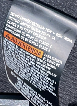
The rating of the current adapter is 120v 60hz 770ma, output of  20v 1A.


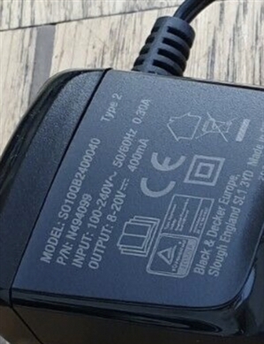
However the UK versions are slightly different for B&D and Stanley they are 
cadc4d5b8de9e1b602f50943981cd410-huge-img_c4561835f81f-1.jpg
US Version
a3a087d1ed79a6870987e2b850f06a88-huge-img_553f85738e3c-1.jpg
UK Version

Was thinking of getting something like - https://www.aliexpress.com/item/4001159381316.html?spm=a2g0o.productlist.0.0.45a66bceNzJeIa&algo_pvid=7d9330ae-94ea-4c45-baac-f128cd8e3545&algo_expid=7d9330ae-94ea-4c45-baac-f128cd8e3545-0&btsid=0b0a557216156484926828136e4e91&ws_ab_test=searchweb0_0,searchweb201602_,searchweb201603_


What be the best to get? is that one ok?
  • If you want to match the existing power supply, it needs to be 20V, 1A.  Make sure the plugs match on the DC side, and check the polarity of the plug.


    You might get away with a cheap 230V to 120V step down transformer.  But European mains is 50Hx, not 60Hz, so it's not guaranteed to work.
  • More info needed - is this thing a battery charger that has all the call failure detection shut down and voltage monitoring, or just a power supply and the battery management is handled in the nailer ?


    If the former a dumb 20V supply may do, but it needs to be as above, the right voltage and current.

    If it is really a battery charger, then you'd need to be very  careful about substitution.


    M

  • Former Community Member
    0 Former Community Member
    85ccc2ff42fabf83f2e5e14e920f33a3-huge-936884f2-d427-41d9-809a-245613f07c94.jpg

    The full image is attached, I’ll open her up abs take a pic of the charger end. I did this before abs saw it had a pcb in it. So I assume the adapter/plug part is just down to 20v and this little board does everything else. 


    I don’t think it’s in the battery but probably in the charger. However I will check and come back.
  • Another thing that's often not said on the label is that it could be a regulated or unregulated 20V supply.  Unregulated supplies can be cheaper, and the manufacturer has cost-optimised it to ensure that the voltage drop under load matches what the actual load needs.
  • Former Community Member
    0 Former Community Member
    9dc338f7149393a03affa7f389b644c3-huge-image.jpg
    f875da0b966d8fb6098e8d01b20244cf-huge-image.jpg

    Once opened this is what is inside, so I think the transformer is just that.
  • Former Community Member
    0 Former Community Member
    Had another though, would it be easier to open the plug and convert it to be able to accept 240v 50hz.  I saw a couple of videos that shows how someone did this by changing the capacitor on the board. Is this really as simple as it is to do?

    5ad778de55ed6733d663cfad818e8422-huge-img_9301.jpg

  • No.

    Well, only in the odd designs that just happen to be that way,

    More generally, not unless you understand the circuit before you. I suspect the transformer ratio is fixed for 110V, and we do not know the primary to secondary insulation quality.  At the top mains comes in, and meets a MOV. This will probably be set to limit at about 130-150V RMS, and will not appreciate 230. Not visible, but perhaps on the back is a rectifier. Then we have two high voltage caps and a common mode choke. (check the voltage rating on the caps)

    It may be a voltage doubling rectifier,  to 300v or so, if so you might be able to substitute  bridge, but it may already be a bridge creating 140VDC or so.

    So the DC rectified mains at either 140V or so,or more like 300, depending, then gets chopped and applied to the transformer.

    There seems to be a single secondary side diode rectifying the chopped waveform and the green low voltage capacitor on the secondary side, and a little ring choke.

    Then there is an optocoupler (black 4 legs) presumably providing feedback to the primary chopping circuit, not visible, to give the regulation.

    as well as unknown stuff on the back, there may be more under the glue.

    The blue caps (left) are required to reduce the switchign spikes breaking onto the output, again they need to be rated to far higher than you need as in effect they connect ipout to output.


    The smaller PCB is probably a charge balancer - this puts a bleed resistor across which ever cell (or cells) charges first, so they are not damaged by over charge and over  voltage while its slower charging mates catch up. It may or may not actually regulate.

    you could look up the data sheets of the chips - googling chip numbers us usually quite informative.

    M.
  • Former Community Member
    0 Former Community Member
    I did manage to change the capacitors, fuse and varistor and it has been working well, the only issue now is I have to locate a suitable case for it. 


    Interestingly enough it is the same as the Black and Decker and the Stanley they produce for the UK market the only difference being the plug.