You cannot post a reply to this discussion. If you have a question start a new discussion
Earthing of VSAT dishes
Former Community Member
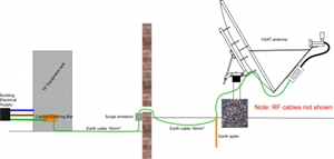
I am trying to apply the principles of BS 7671 to VSAT installations in Africa. My chief concern is the connection of the VSAT dish to the electrical supply provided by the customer. The standard practice I've adopted is shown in the attached sketch. The metallic parts of the dish are connected with copper conductors and then to an earth spike (or spikes) near the dish foundations. The earth cable is then run (either in a conduit of buried) to the equipment building. At the entry to the building, the earth cable is used by surge arrestors fitted to the RF cables. The earth cable then runs to an earth bar fitted into the equipment cabinet. The mains supply to the equipment is supplied by the customer, the earth of which is also connected to the cabinet's earth bar. The power supplied by the customer may be from a generator 100% of the time, or more like comes from the town's municipal supply, These supplies are often erratic so a back-up generator is often in use, and as a matter of course we always fit an on-line UPS. Is this approach sensible? Thanks for any assistance.
Maybe slightly off the point, although i noticed emphasis on the 16mm2 green wire. I had a chat sometime ago about the problems associated with earthing African telephone switching stations. Lightning strikes,very common there, would damage the telecomms equipment until he designed an earthing grid that encompassed the perimiter of the various buildings he was supervising.
Thanks for the pointer I'll try the other forum. The supplies are mainly TT, but some very remote sites are powered by a local generator almost full time. The protective devices are usually RCDs. The earthing is to give some protection in case of lightning. However, if the location is very prone to electrical storms an air terminal on a near-by structure is usually also provided. This will have it's own earthing system. The dishes are usually ground based. The class of the power supply is difficult to determine as the indoor equipment comprises six or seven modules each with their own mains supply. The equipment mounted on the dish usually gets its power from the RF coax cables. However, sometimes the dish mounted amplifier (BUC) is 240v powered, either with an SWA cable run into the unit, or via a 240v ac/48v dc power supply mounted on the antenna mount.
Thanks for the pointer I'll try the other forum. The supplies are mainly TT, but some very remote sites are powered by a local generator almost full time. The protective devices are usually RCDs. The earthing is to give some protection in case of lightning. However, if the location is very prone to electrical storms an air terminal on a near-by structure is usually also provided. This will have it's own earthing system. The dishes are usually ground based. The class of the power supply is difficult to determine as the indoor equipment comprises six or seven modules each with their own mains supply. The equipment mounted on the dish usually gets its power from the RF coax cables. However, sometimes the dish mounted amplifier (BUC) is 240v powered, either with an SWA cable run into the unit, or via a 240v ac/48v dc power supply mounted on the antenna mount.
Brian
Hello Brian, you will get some replies soon when the experts get back from the pubs and night clubs.
Or at least when the login server problem is fixed.
Well the sites on Genset will be TN-S I presume, as there are more than piece of kit from reach genset and class 1 gear outside, so I'd expect an NE link at the genset, and an earth electrode of some kind.
BS7671 may not be the best standard to be looking at for this, or at least it will not provide an exhaustive list of what needs considering. There are two distinct problems, the ADS and the lightning. On a genset ADS will be funny anyway, as the prospective fault current will be quite limited.
In both genset and TT supply, the use of an RCD is key.
Lighting. To be under the cover of an air terminal some way away is probably the most sensible, but even so those other cables (RF not shown) could become quite significant in terms of importing or exporting a violent change in potential to some other place or equipment you are not expecting, as there will be quite a large and variable voltage slope across the ground in a lighting state.
As drawn there is nothing leaping out as wrong, but what are the surge arrestors doing - all they do is connect two things together if the voltage exceeds some break over limit - I'm not clear what the 2 things are. Perhaps one is a kind of local earth voltage via that long lead, what is are the other(s)
You may also wish to have surge protection that clamps the mains voltage when it comes in, so it is clipped in some known way if it tries to exceed its voltage by a large margin.
I think there is more to know in terms of the rest of the installation to understand the issues involved.
That is a similar arrangement adopted here in the UK for mobile phone masts. A lightning protection (LPS) rod at the highest point on the mast with the mast connected to earth electrodes at the base. The signal co-ax cables have inline surge protection before they enter the equipment cabin. All the mains supply to the equipment racks has Type 1 and Type 2 surge protection with any metallic parts of the cabin, external mains feed pillars, any metallic fence all connected to auxillary electrodes all connected together with tape and to the LPS earthing.
I am no expert but I think it would be better to have your surge arrestor on the earth outside the building rather than inside. Also I am not over keen in the long runs of earth from your surge arrestor to the earth electrode. I would be much happier to see another electrode directly connected to your surge arrestor outside the building. In the UK BS 7671 requires the total length of the connection of a live conductor to a Surge Protection Device and the earth connection ideally should not exceed 0.5m and not to exceed 1m. Dumping any transient to earth outside the building would be my preference.
I am no expert but I think it would be better to have your surge arrestor on the earth outside the building rather than inside. Also I am not over keen in the long runs of earth from your surge arrestor to the earth electrode. I would be much happier to see another electrode directly connected to your surge arrestor outside the building. In the UK BS 7671 requires the total length of the connection of a live conductor to a Surge Protection Device and the earth connection ideally should not exceed 0.5m and not to exceed 1m.
If a few milli Ohms of 1m of cable is an impedement to ideal SPD operation, I can't quite see how an electrode with dozens of Ohms to Earth is going to make a significant difference (skipping over that plain resistance is only part of the story of impedance with rapidly rising spikes). In my head SPDs are less about dumping surges to true earth so much as limiting the voltage difference between the live/signal conductors and the installation's protective conductors - pulling the protective system up as much as pulling the other lines down. Shades of the old equipotential zone - which may well be a long way from true earth potential during faults. I think the important bit if the lenth of the 'branch' between the SPD and the connections feeding the equipment/installation being protected - keep those below 0.5m and the other lengths matter much less I think.
This is true - but you are quite right in saying the correct way to think of this is the equipotential zone, where it all gets pulled around together, rather than being well earthed to anything absolute - which is why if you have lengths of coax cable running to other rooms or even other buildings, you can see surprising potentials in places you'd rather not. Operators of cable TV networks put very deliberate breaks and RF isolating transformers in for this sort of reason.