This discussion is locked.
You cannot post a reply to this discussion. If you have a question start a new discussion

Proximity pilot

59df04775ff4a8d5786e6798f8b35390-huge-b8cb9e0d-e68a-4ec5-8744-4754774656f2.jpg
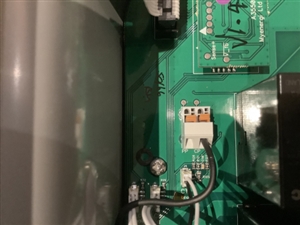
  • Proximity pilot wire is absent on this EV charger. Why?
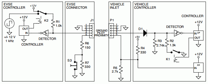
  • It may be handled in the body of the trailing socket  if the lead is captive, and is so it saves a wire in that cable - all it is is a resistor to gnd whose value is switched  sets an upper limit to tell the car how much current it can draw, on a microswitch or a break early pin (S3 here), so the car charger has hopefully seen the resistance rise and stopped taking big amps, before the high current contacts are withdrawn.


    EDITED to correct an erroneous  explanation


    Regards Mike.
  • Ah! first class, as always Mike! So it would seem that the PP connection is at the discretion of the EVSE manufacturer as to whether the arrangement is in the Charge point or in the plug. This in turn would mean that the leads would not be standard to all charge points. I noted 5 conductors on a single-phase lead from one manufacturer (p,n,e,cp,pp) and 6 on this three-phase one from a different manufacturer (p,p,p,n,e,cp). 

    I thought the function of the pp was just to confirm proper contact and the control pilot was the part of the handshake that arranged the level of charge?
  • Come to think of it, the single-phase unit was untethered and the 3-phase tethered.
  • I imagine when new the controller and the cable are supplied as a pair, it works just fine, and I can see the attraction of one less core in the cable

    I think this means that folk have to be careful if you replace the cable that is set up to match the EVSE - it would be easy to fit the wrong one, and 'lie' to the car so it draws current from the mains supply when it is not intended, or it never comes on at all.

    I assume at some point someone will damage a lead or connector and make this error when replacing it and get very confused.

    And yes sorry, I was a bit dopy last night, the CP sets the power - the 'information direction' of the  PP is only  from charger to car, and you are right the signal is much cruder (more go/ no-go) than the control  pilot (CP) which is a bidirectional communications in the sense that the charger alters the duty cycle of the tone to indicate the charger power, and the car can reply back to the EVSE by modulating the load it presents.

    I have edited my response so it is not too misleading for anyone else reading quickly.


    However, the fact remains the resistor needs to be the right value, and fitting two, both in plug and at PCB,  or none,  will bring it all to a shuddering half.


    If only the use of the pilot pin on CEEFORM connectors was this well standardised.

    M.


  • mapj1:

    It may be handled in the body of the trailing socket  if the lead is captive, and is so it saves a wire in that cable - all it is is a resistor to gnd whose value is switched  sets an upper limit to tell the car how much current it can draw, on a microswitch or a break early pin (S3 here), so the car charger has hopefully seen the resistance rise and stopped taking big amps, before the high current contacts are withdrawn.


    EDITED to correct an erroneous  explanation


    Regards Mike.


    Can I get that on a coffee mug?


  • yes

    Mike