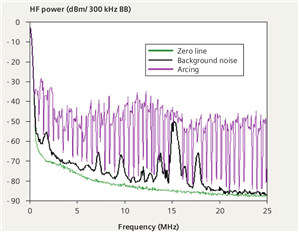
It's occurred to me that if AFDDs work by spotting distortion in the a.c. current waveform that's passing through the device, then they're likely to see the same effect if series arcing is occurring upstream (with a decent sized load downstream).
If that's the case a decent DNO's crackle could trip out a significant number of final circuits if they happened to be loaded at the time.
Or are AFDDs cleverer than that? (e.g. do they look for an undistorted incoming voltage as well as a distorted current?)
As many of the dimming and flickering I've seen has been down to DNO loose connections, there could be a lot of nuisance tripping with these new devices if my worry is correct.
- Andy.