This discussion is locked.
You cannot post a reply to this discussion. If you have a question start a new discussion

ABB MCCB and 5 seconds disconnection.

Hi all,

Looking for a bit of clarification on disconnection times here. I have information on an ABB Mccb that has been listed as failing on maz zs.

The max zs referenced for the unit is 0.07 ( 250a TMD TP set at maximum) the measured zs is 0.08, however, the max Zs is listed for 0.4 and 5 seconds.

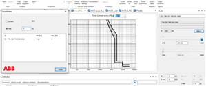
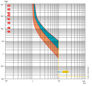
Looking at the time current curve on the mccb once you hit 3.5.times 250a you are in the thermal tripping zone of the mccb. Using the curves software from ABB it indicates a 5 second disconnection can be achieved with 1.66ka.


How do I work this out? is the MaxZs listed as the same for both disconnection times because the only way to ensure a 5sec disconnection is to have an instantaneous trip?
  • 983e19a7de08c7c219d320ec2ddca2f8-original-curve.png
  • 8905507d8c9ce0e3dd39ab44f8072880-original-curve2.png
  • I'm perhaps not reading the graphs etc. correctly, but it looks to me like it's saying for 5s disconnection you'd need something between 1.66kA and 3kA. There's always a band or envelope of acceptable time/current characteristics and any single device's performance may fall anywhere within that band. So to guarantee 5s disconnection you'd need 3kA - with equates to Zs of just over 0.07 (taking Cmin of 0.95 into account).


    The 1.66kA figure is more useful when you're trying to obtain discrimination (selectivity) with downstream devices or ensure switch-on surges don't cause nuisance tripping.


      -  Andy.
  • Hi there,  trying to piece it together without knowing the installation, or that breaker family, or the software, terribly well, so please forgive my opening with a few "obvious" questions.

    Has a Zs of 80 milliohms been measured as round loop at the far point of the circuit this breaker supplies ? 

    (and measured with what kit, and how well does that tally with the expected resistance for the length and size of cable involved?  I ask that because it reads you are only in or out by a few milliohms here, and to get a reading of that sort of precision can be rather fraught - just cos the meter has that many digits does not always mean that the last few digits have more  value than pulling the handle on a  fruit machine in the arcade depending how it was done )

    This is an adjustable breaker, but it is wound up to the max, which is 250A ? (so we expect the 'instant trip' to be some multiple of that)  So Ir is set to 1,  and is Im also adjustable and if so what is it fixed at or adjusted to ? (Im is the "magnetic" trip multiplier Ir is the thermal one )

    If for example the Im multiplier is set or fixed to  10, then you need 2.5kA to give an instant trip , and that looks rather like one of your graphs  is suggesting, and for fault current below that, the time will be some seconds.

    The supply is TN something and there is no earth fault relay or RCD anywhere, so you are relying on this breaker to do the deed for LE faults as well as overloads ?


    So if all these things are true, then with 70 milliohms and 230V L-E your PSSC is more like 3.2KA,  and with 80 milliohms more like 2.8kA so really you should be OK - but nowadays folk allow for lower line voltage  and instrument tolerances etc, and decide the PSSC may be a bit lower, and after that correction, then it fails, but only just.


    You could re-measure, especially if the cable  calcs show it should be a lot less.  (is there really 20 volts drop on full load that would really suggest Zs reading is true ?)

    You could wind the I max down by 10% and see if anyone notices.  Or if you have control over Im, just wind that in a bit.

    You could investigate if there is any mileage in additional earth paths to lower Zs

    You could  consider the addition of an earth fault relay.

  • It's an installation already in service and this is from a EICR. The install is around the 5 year old mark.

    Yes it has been measured as 0.08 Zs with a multifunction test unit.

    I cannot comment on the length of run.


    I seem to be getting issues of this nature across a lot of buildings on site. Baring in mind the majority of buildings are no more than 6 years old. It may be one to refer back to the contractors responsible. Sadly, the o+m info is missing any design calculations to enable a cross ref of what was expected.


    Am I correct in assuming that if the fault current was 8xIn the operating time would be anything between 0.7 to nearly 11 seconds ?


    Thanks all, for helping clarifying this for me. It's a bit easier to understand it with a few more opinions.


  • In terms of the operating time, yes it looks quite broad once you are the 'not really instant' part of the curve, assuming the curves you have posted are for the right breaker and setting case, then I agree with your conclusion..


    However, before panicking, and if you are seeing a lot of marginal fails like this on test,  and yet really there are no volt drop issues or visual signs of things cooking it is worth pointing out that an MFT, depending on the model, may or may not be accurate to tens of milliohms, even when meeting the maker's factory test spec with brand new clean and nulled leads and nice bolted joints (not scratchy probes on slightly tarnished screw heads). That back page of the meter  handbook about accuracy and tolerances  is the first thing to check, and/ or the length and cable type.


    (For example This dataasheet from Megger  suggests an accuracy on lop tests of  5% of reading +/- 5 counts in the least significant digit.

    So if the reading on the display was 0.080  then the real value to generate that could lie  anywhere between 0.071 to 0.089   (5% is 4 in the last place plus another 5 counts),

    OK, but worse, while on a less sensitive setting , if the reading on the display was on a range such that it was showing 0.08 ohms, then that reading could be generated by a true value of anything from 0.03 to 0.13.  Neither would be  considered convincing.  Of course by you add a set of leads that have spent more than  a week in the toolbox and busbars that are no longer golden and bright, the uncertainty rises, usually on the upside.  Your meter may be better, but check.)
  • I concur with Mike. It is unlikely you could get an accurate reading to discriminate between 0.07 and 0.08 with an MFT. They are really only designed for installations to 100A, PSCC and Earth loop at higher ratings are difficult even with all the right instruments on a real installation because you need bolted connections, exactly zeroed leads and high test currents. If this is a submain as I suspect, the exact disconnection time is probably not the most important thing. If it is 6 seconds not 5, then nothing particularly bad is going to happen. Do you have the original EIC? What is the quoted figure, because if it is close, it is probably better than the one you have measured. The correct way to test this without specilised equipment is to disconnect the live conductors, substitute a high current power supply and pass say 10-50A (Measured to 1% with calibrated meters) and measure the volt drop with a high accuracy millivoltmeter. Now you have the real resistance and it will be lower than you expected. You now also take the path loop inductance into account (either by measurment or calculation having measured the cable length accurately), and calculate the series reactance. Add and that is the real loop impedance. You can use an AC current, but now adjustment and accurate measurment are more difficult (no clamp meters here!).
  • mapj1:

    (For example This dataasheet from Megger  suggests an accuracy on lop tests of  5% of reading +/- 5 counts in the least significant digit.

    So if the reading on the display was 0.080  then the real value to generate that could lie  anywhere between 0.071 to 0.089   (5% is 4 in the last place plus another 5 counts)


    This is odd! Would that be the case with an analogue meter?


    The Megger MFT's minimum value for EFLI is 0.01Ω so if the reading is anything up to 0.06Ω, it could be zero. Or you go to a TT installation where the EFLI is 100Ω and it could be anywhere between 90Ω and 110Ω. It's that last digit which troubles me. If the machine has measured to an accuracy of +/- 5% (much worse than a simple ruler!) why can it not express the value accurately?


  • why can it not express the value accurately

    I suspect the problem is not so much being able to express the value accurately - so much as measuring it accurately in the first place. Usually for a loop test they're trying to measure tiny changes in voltage when applying or removing a modest load - and somehow having to distinguish the intended variation from all the other changes that are happening in the local part of the network and indeed the grid generally, variability in the quality of the connection between the test probes and the installation, and probably a dozen other variables.

        - Andy.
  • This is odd! Would that be the case with an analogue meter?


    Not perhaps so obviously, but yes, when you are crammed in near the zero of the scale. If the moving coil meter has say a 100 degree maximum deflection (makes the sums easy but is about right for most real meter movements) ,  then three significant figures  would be an angular change of  0.1 degree. Now 1 degree is 1mm graduations on a 50mm long needle, so unless you have a massive instrument, then  I suggest that while 2 significant figures (1%) is quite easy, with mirrors to avoid parallax and so on, three is probably impossible.  So we can see a change of 1%,  if the thing being measured is near full scale, or for the hard case the spec must meet,  if it is just after a range change, then it depends on the range steps. Good analogue meters had a 1,3,10,30,100 scaling, so at worst the thing you are measuring might be just over 100% of the range below, and so about 30-35% of full scale so that 1 degree mark is more like 3%, and then we come to the equivalent of the absolute offset of 5 counts - how accurately can you 'zero' the analogue meter  probably a degree or so again?


    Analogue to Digital conversion (ADC)s have the same problem and as far as I know all common digital meters either use dual slope integrations or successive approximation (  A long read here for what that means ) Both types suffer from non-linearity, step size errors, and DC  offsets to some extent, so you have some equivalent abberations, before you even look at how well it has been calibrated and against what, and the uncertainty of the actual circuit being tested - as described above.

    They do pretty well all things considered.